TECHNICAL BULLETIN
INSTALLATION INSTRUCTIONS FOR REPAIR PARTS
WARNING!
This repair kit shall be installed by a qualified service agency in accordance with the manufacturer’s instructions and all applicable codes and requirements of the authority having jurisdiction. The information in these instructions must be followed to minimize the risk of fire or explosion or to prevent property damage, personal injury or death. The qualified service agency is responsible for the proper installation of this kit. The installation is not proper and complete until the operation of the appliance is checked as specified in the manufacturer’s instructions.
INTRODUCTION
These instructions are intended for the installation of parts for units with Flammable Vapor Ignition Resistant Technology (FVIR). The end result of using these instructions and this kit is to effect proper repairs of these flammable vapor ignition resistant water heaters.
Please make sure you have the correct kit number for the model water heater you have before starting the installation.
IMPORTANT
The installation of this kit requires ability equivalent to that of a licensed tradesman in the field involved. Air supply, venting and gas supply are required. These instructions as well as the manual that came with the water heater must be read thoroughly and understood before attempting any of the repairs covered herein.
All WARNINGS and CAUTIONS in both these instructions and the manual that came with the water heater must be carefully observed at all times.
WARNING!
Improper installation could result in a hazardous condition such as explosion or carbon monoxide poisoning resulting in serious personal injury or death.
PREPARATION
Before beginning repairs do the following:
1. Shut off the gas supply to the water heater.
2. Rotate the thermostat dial on the water heater control counter-clockwise until the main burner ignites and burns off all residual gas in the control and supply lines.
3. Rotate the thermostat dial clockwise back to the “PILOT LIGHTING” position.
Tools Required:
- 3/8”, 7/16”, and 3/4” Open-end wrenches
- 3/8” Nut driver
- Phillips-head screwdriver
A. Removing Old Burner Assembly:
1. Remove outer door.
2. Remove nuts holding inner door in place with 3/8” nut driver.
3. Unplug wire from igniter assembly mounted on the top of the gas valve.
4. Loosen flare nut holding thermocouple to bottom of gas valve with 3/8” open-end wrench and pull down to remove.
5. Loosen flare nut holding pilot line to bottom of gas valve with 7/16” open-end wrench and pull tube down to remove.
6. Loosen flange nut holding burner tube to bottom of gas valve with 3/4” open-end wrench and pull down to remove.
7. Grasp burner tube and remove burner assembly through inner door opening, see Figure 1.
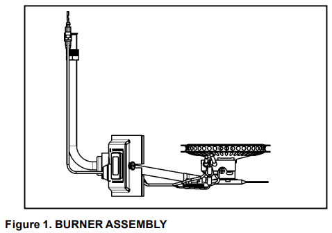
B. Installing New Burner Assembly:
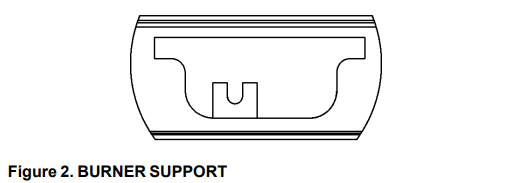
1. Insert new burner assembly through the door opening being careful not to damage the door gasket on the studs, see Figure 1. The burner tube must rest in the support bracket inside the combustion chamber, see Figure 2. Be sure the igniter wire and pilot tubing do not bow up where the flame may damage them. The inner door should fit with the studs extending through the slots in the door. Check to see if the door gasket extends uniformly around the door, see Figure 3. This will ensure that the gasket is not folded and properly seals the combustion chamber
2. Put the burner tube into the bottom of the gas valve and tighten the flare nut. Ensure that the burner tube remains in the support bracket inside the combustion chamber.
3. Insert the pilot tube into the bottom of the gas valve and tighten the flare nut.
4. Insert the thermocouple into the bottom of the gas valve and tighten the flare nut.
5. Plug wire from combustion chamber into igniter assembly located on the top of the gas valve. Wire should be routed behind burner tube and gas supply line.
6. Install serrated flange nuts on studs and tighten to hold inner door in place.
7. Make sure burner tube boot is on flange on inner door and pilot assembly grommet is secure in the hole in the inner door.
8. Light pilot following the lighting and operating instructions on the front surface of the heater.
9. Install outer door.
C. Replacing Burner Head: (See Figure 4)
1. Follow steps 1 to 7 in A above to remove burner assembly,
2. Remove the Phillips-head screw holding the TCO bracket to the burner tube bracket, see Figure 5.
3. Remove the Phillips-head screw holding the pilot bracket to the burner head, see Figure 6.
4. Remove the two Phillips-head screws holding the burner head to the burner tube assembly, see Figure 5
5. Pull the burner tube boot off the flange on the inner door and remove the burner tube assembly.
6. Push the pilot assembly grommet out of the inner door towards the combustion chamber.
7. Pull the igniter wire, thermocouple, and pilot tube through the inner door hole.
8. Remove the gasket from the inner door and replace it with a new gasket.
9. Feed the igniter wire, thermocouple, and pilot tube through the inner door hole.
10. Push the grommet into the inner door hole making sure the door fits into the groove in the grommet.
11. Insert the burner tube assembly through the inner door and place the boot on the inner door flange.
12. Fasten the new burner head to the burner tube assembly using two Phillips-head screws, see Figure 5.
13. Fasten the pilot bracket to the new burner head with a Phillips-head screw, see Figure 5.
14. Fasten the TCO bracket to the burner tube bracket with a Phillips-head screw, see Figure 5.
15. Follow steps 1 to 9 in B above to install the burner assembly.
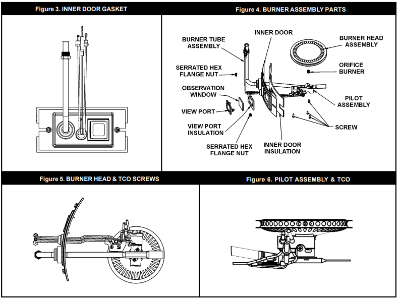
D. Replacing Burner Orifice: (See Figure 4)
1. Follow steps 1 to 7 in A above to remove burner assembly,
2. Remove the Phillips-head screw holding the TCO bracket to the burner tube, see Figure 5.
3. Remove the two Phillips-head screws holding the burner head and pilot assembly to the burner tube assembly, see Figure 5.
4. Pull the burner tube boot off the flange on the inner door and remove the burner tube assembly. 5. Remove the orifice from the burner tube and replace it with the new one using a 3/8” open-end wrench, see Figure 4.
6. Push the pilot assembly grommet out of the inner door towards the combustion chamber, see Figure 3.
7. Pull the igniter wire, thermocouple, and pilot tube through the inner door hole.
8. Remove the gasket from the inner door and replace it with a new gasket, see Figure 3.
9. Feed the igniter wire, thermocouple, and pilot tube through the inner door hole.
10. Push the grommet into the inner door hole making sure the door fits into the groove in the grommet.
11. Insert the burner tube assembly through the inner door and place the boot on the inner door flange.
12. Align the burner head mounting bracket holes with the holes in the burner tube bracket and fasten with two Phillips-head screws, see Figure 5.
13. Fasten the TCO bracket to the burner tube bracket with a Phillips-head screw, see Figure 5.
14. Follow steps 1 to 9 in B above to install the burner assembly.
E. Replacing Burner Tube Assembly: (See Figure 4)
1. Follow steps 1 to 7 in B above to remove burner assembly.
2. Remove the Phillips-head screw holding the TCO bracket to the burner tube, see Figure 5.
3. Remove the two Phillips-head screws holding the burner head and pilot assembly to the burner tube assembly, see Figure 5.
4. Pull the burner tube boot off the flange on the inner door and remove the burner tube assembly.
5. Remove the orifice from the burner tube assembly with a 3/8” open-end wrench, see Figure 4.
6. Push the pilot assembly grommet out of the inner door towards the combustion chamber.
7. Pull the igniter wire, thermocouple, and pilot tube through the inner door hole.
8. Remove the gasket from the inner door and replace it with a new gasket, see Figure 3.
9. Feed the igniter wire, thermocouple, and pilot tube through the inner door hole.
10. Push the grommet into the inner door hole making sure the door fits into the groove in the grommet.
11. Install the orifice in the new burner tube assembly with a 3/8” open-end wrench, see Figure 4.
12. Insert the new burner tube assembly through the inner door and place the boot on the inner door flange.
13. Align the burner head mounting bracket holes with the holes in the burner tube bracket and fasten with two Phillips-head screws, see Figure 5.
14. Fasten the TCO bracket to the burner tube bracket with a Phillips-head screw, see Figure 5.
15. Follow steps 1 to 9 in B above to install the burner assembly.
F. Replacing Pilot Assembly: (See Figures 3 through 6)
1. Follow steps 1 to 7 in A above to remove burner assembly.
2. Remove the Phillips-head screw holding the TCO bracket to the burner tube, see Figure 5.
3. Remove the Phillips-head screw holding the pilot bracket to the burner head, see Figure 6.
4. Push the pilot assembly grommet out of the inner door towards the combustion chamber.
5. Pull the igniter wire, thermocouple, and pilot tube through the inner door hole.
6. Remove the two Phillips-head screws holding the burner head and pilot assembly to the burner tube assembly, see Figure 5.
7. Pull the burner tube boot off the flange on the inner door and remove the burner tube assembly.
8. Remove the gasket from the inner door and replace it with a new gasket, see Figure 3.
9. Feed the new igniter wire, thermocouple, and pilot tube through the inner door hole.
10. Position grommet on the pilot assembly so that excess tubing/wiring is located on the outer side of the inner door. Note: that replacement pilot assemblies may be longer than factory installed parts.
11. Push the grommet into the inner door hole making sure the door fits into the groove in the grommet.
12. Insert the burner tube assembly through the inner door and place the boot on the inner door flange.
13. Fasten the pilot bracket to the burner head with a Phillipshead screw, see Figure 5.
14. Fasten the TCO bracket to the burner tube bracket with a Phillips-head screw, see Figure 5.
15. Align the burner head mounting bracket holes with the holes in the burner tube bracket and fasten with two Phillips-head screws, see Figure 5.
16. Follow steps 1 to 9 in B above to install the burner assembly
G. Replacing Inner Door: (See Figure 4)
1. Follow steps 1 to 7 in A above to remove burner assembly.
2. Remove the Phillips-head screw holding the TCO bracket to the burner tube, see Figure 5.
3. Remove the two Phillips-head screws holding the burner head and pilot assembly to the burner tube assembly, see Figure 5.
4. Push the pilot assembly grommet out of the inner door towards the combustion chamber.
5. Pull the igniter wire, thermocouple, and pilot tube through the inner door hole.
6. Pull the burner tube boot off the flange on the inner door and remove the burner tube assembly.
7. Place the new gasket on the new inner door, see Figure 3.
8. Feed the igniter wire, thermocouple, and pilot tube through the inner door hole.
9. Push the grommet into the inner door hole making sure the door fits into the groove in the grommet.
10. Insert the burner tube assembly through the inner door and place the boot on the inner door flange.
11. Align the burner head mounting bracket holes with the holes in the burner tube bracket and fasten with two Phillips-head screws, see Figure 5.
12. Fasten the TCO bracket to the burner tube bracket with a Phillips-head screw, see Figure 5.
13. Follow steps 1 to 9 in B above to install the burner assembly.
H. Replacing Inner Door Gasket: (See Figure 4)
1. Follow steps 1 to 7 in A above to remove burner assembly.
2. Remove the Phillips-head screw holding the TCO bracket to the burner tube, see Figure 5.
3. Remove the two Phillips-head screws holding the burner head and pilot assembly to the burner tube assembly, see Figure 5.
4. Push the pilot assembly grommet out of the inner door towards the combustion chamber.
5. Pull the igniter wire, thermocouple, and pilot tube through the inner door hole.
6. Pull the burner tube boot off the flange on the inner door and remove the burner tube assembly.
7. Remove the gasket from the inner door and replace it with the new gasket, see Figure 3.
8. Feed the igniter wire, thermocouple, and pilot tube through the inner door hole.
9. Push the grommet into the inner door hole making sure the door fits into the groove in the grommet.
10. Insert the burner tube assembly through the inner door and place the boot on the inner door flange.
11. Align the burner head mounting bracket holes with the holes in the burner tube bracket and fasten with two Phillips-head screws, see Figure 5.
12. Fasten the TCO bracket to the burner tube bracket with a Phillips-head screw, see Figure 5.
13. Follow steps 1 to 9 in B above to install the burner assembly.