TECHNICAL BULLETIN
Field Installation of Draft Hoods - Standard Gas Water Heaters
General
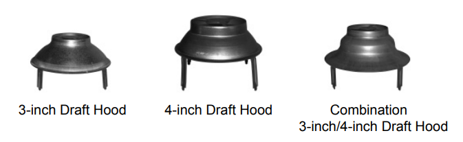
The purpose of this bulletin is to show installers how to properly connect draft hoods to single- and double-wall (Type B) vent pipe. These instructions cover 3-inch, 4-inch, and combination draft hood sizes.
A draft hood is critical to the operation of a gas water heater. (It is attached between the heater’s flue outlet and the vent pipe.) When properly installed, the draft hood cools the combustion products and allows them to fl ow safely from the building. It also protects heater operation during updrafts and downdrafts that are caused by indoor/outdoor air pressure differences.
WARNING
- The venting system shall comply with applicable local and state/provincial codes. The venting system shall also comply with the current edition of the National Fuel Gas Code ANSI Z223.1/NFPA 54 (U.S.A.) or the Natural Gas and Propane Installation Code CAN/CSA-B149.1 (Canada).
- Each standard vent gas water heater is supplied with a specific draft hood. This ensures the safe, correct operation of the water heater. However, the draft hood must be installed correctly.
- Do not use a draft hood other than the one that is supplied with the water heater.
- Do not re-use any previously installed draft hood. Previously used parts should be discarded.
- Do not modify, cut, or bend a draft hood during installation.
- Do not block or restrict the open areas around the draft hood. Do not store or place objects on top of the water heater.
- Install the draft hood securely to the water heater and flue pipe according to the installation instructions. These instructions were provided with the water heater.
- Do not use fl ex vent pipe or dryer vent pipe.
- Vent pipe should be made of galvanized steel. Do not use aluminum vent pipe.
- Always wear work gloves when working with sheet metal parts.
Tools and Materials
The following tools and materials may be required to install the draft hood and vent pipe. Other tools and materials may be needed.
- Work Gloves
- Flat-ended pliers
- Water Heater Installation Manual
- 1/4-inch hex nut driver
- Screw driver with fl at tip
- Powered screw driver tool (optional)
- Tape measure (for checking sizes)
- Sheet metal cutting tools (optional)
Types of Draft Hoods Covered in this Bulletin
Types of Vent Pipe Covered in this Bulletin
- Single Wall - Galvanized Steel
- Double Wall (Type B) - Galvanized Steel
Installation Procedure
Step 1:
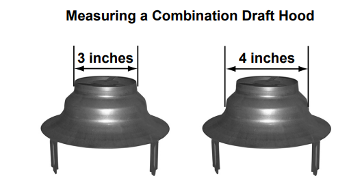
Determine the size of the draft hood.
To determine the size of a draft hood, measure across the portion that will fit into the vent or vent connector. Note: Vent connection will be covered later.
Example:
Step 2:
Install the draft hood to the water heater according to the installation manual.
NOTE: There are two methods for securing a draft hood. Use only the method that applies to your water heater model.
- Lock-in Type: Some draft hoods have notches at the bottom of each leg. Simply align the legs of the draft hood with the slots in the top of the water heater. Insert the legs, then rotate the draft hood. Ensure that the draft hood is secure before you proceed.
- Push-in Type with screws: Most draft hoods are designed to be secured with screws (which are provided). Align the legs of the draft hood with the slots in the top of the water heater. Insert the legs into the slots, then secure them with screws as described in your installation manual.
Step 3:
Connect the draft hood to the venting system as described below.
IMPORTANT: The inside diameter of the vent pipe or draft hood connector may vary slightly by manufacturer. Always verify that vent connections are secure and air tight.
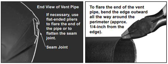
In instances where correctly-matched pieces will not fit together, use flatended pliers to flare the end of the pipe or flatten its seam joint. However, do not modify, cut, or bend the draft hood.
Step 3 (continued):
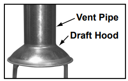
A. Fit the female end of the vent pipe over the draft hood as shown below. Note that you may need to adjust or reposition the vent pipe during this process. If you are connecting the draft hood to Type B vent pipe or to vent pipe of a different size or brand, read the Coupling section before you proceed.
B. Verify that all vent connections are secure and air tight.
C. Secure the vent pipe to the draft hood with self-drilling screws. Also secure any new sections of vent pipe.
Use a minimum of three screws per connection. Screws should be evenly spaced. For example, three screws should be spaced at 120 degree increments around the perimeter of the vent pipe.
IMPORTANT: Only use screws that are 5/8” long or less in length.
Coupling
The opening of your draft hood will be either 3-inches or 4-inches in diameter. (You measured the diameter during Step 1 of the Installation Procedure section.)
- If you are connecting double wall (Type B) vent pipe to the draft hood, you must use a Type B draft hood connector. Without this connector, double wall vent pipe will not fit the draft hood properly. See Type B Draft Hood Connectors.
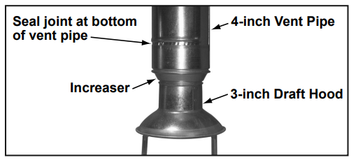
- Compare the size of your draft hood opening to the size of the vent pipe. If the vent pipe has a wider diameter than the draft hood, use an adapter to connect them. See example below.
When transition to a larger vent size is required, the vent transition connection must be made at the draft hood outlet. Do not connect a 4-inch draft hood to 3-inch vent pipe. A draft hood must only be connected to an equal or larger-sized vent pipe (as allowed by code).
Only use the draft hood that is supplied with the water heater.
- When two vent pipes are made by different manufacturers, they may not fit together properly. In such cases, use a universal adapter to join the vent pipes. (Follow the manufacturer’s instructions and all applicable code.) However, do not use a universal adapter to join the draft hood to the vent pipe. Always verify that the vent connections are secure and air tight.
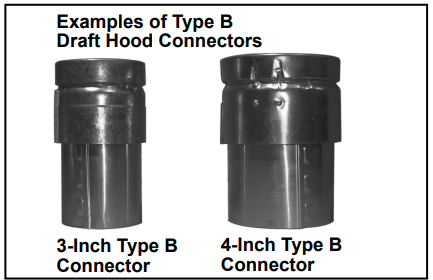
Type B Draft Hood Connectors
Double wall (Type B) vent pipe will not fit draft hoods properly. To ensure a secure connection, use a
Type B draft hood connector between double wall vent pipe and the draft hood. Type B vent connectors are available in various sizes, including those shown below.
The following graphic shows a typical connection between a draft hood and Type B vent pipe.
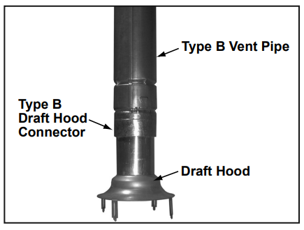
NOTE: Be sure to secure the connections as described in step 3 of the Installation Procedure section.